SENIOR THESIS
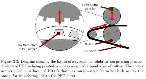
One of the requirements for my bachelor's degree was to write a senior thesis. I wrote my thesis on a project I had been working on for about a year - I designed and built a test platform for conducting dynamic testing of polydimethylsiloxane (PDMS). The thesis contributed to a larger body of research in Professor David Hardt's lab, which was developing manufacturing processes for micro-contact roll printing of different polymers for producing MEMS devices. Prof. Hardt and his team wanted to develop a way of printing large rolls of polymers with very small features so that they could be used for such applications as microfluidics (lab on a chip technology), liquid crystal displays and solar panels. One of the challenges in designing these printing systems is that the polymer has some inherent elasticity and will dynamically respond to the loading applied during the printing process. That means that the printing process must compensate for the motion of the polymer as it is applying the printing force.
Graduate students on Prof. Hardt's team were developing the control systems for these printing processes, but they needed to be able to model the behavior of PDMS so that they could incorporate it into their control logic. That's where my thesis project came in - I designed and built a test platform that could apply the dynamic loads that PDMS would see during printing, and then measure the way PDMS responded to those loads using a linear variable differential transformer (LVDT). I began this project with Spencer Wilson and Chandler Douglas as part of an undergraduate research project.
Mechanical Design Process
Spencer Wilson was responsible for doing the initial design of the test bed. When this project became my thesis I took over the CAD model and built all the parts myself. The gallery below shows the CAD design and the process of building the test bed.
The test bed was built to apply dynamic linear forces to a piece of PDMS. The PDMS was fixed to a top plate that could be considered rigid compared to the PDMS. The plate was fixed to a load cell which was used to measure the amount of force applied to the PDMS. The force was delivered by a shaft driven by a voice coil motor and sliding through a precision air bearing. The LVDT would read the position of the voice coil motor/shaft sub-assembly.
For the basic structure of the test bed, I built the parts on a manual mill out of aluminium. I had also designed some more complex components meant to hold the actuators and sensors, and these I cut from a sheet of aluminum using a waterjet.
Electrical System Design

This project required a combination of sensors, actuators and controllers to work correctly. I wanted to measure both the force applied and the position of the shaft which required a load cell and an LVDT. I wanted to be able to deliver a specific load to the PDMS which required a voice coil motor. Finally, I also wanted to be able to control the entire system using LabVIEW so that I could write a custom control loop.
I set functional requirements for all of my electrical components to ensure that they would meet my project's goals and also communicate with one another. You can see the full selection process in my thesis, and some diagrams and schematics of the final design are shown in the gallery below.
Control System Design
I had to design a LabVIEW control loop for running the test bed. The first step in designing this control loop was modeling every part of the system. I created a mass-spring-damper model for the test bed which is shown in the image gallery opposite. I then transferred that model to LabVIEW and incorporated a control loop for it.

Diagram of the components in the test bed.

Functional requirements and design parameters set for the test bed.

Final design completed.
Diagram of the components in the test bed.
Supporting Documents
Below is a list of supporting documents I wrote as part of my thesis project, as well as the thesis itself.